2011年10月8日星期六

A Memory Allocator

by Doug Lea
[A German adaptation and translation of this article appears in unix/mail December, 1996. This article is now out of date, and doesn't reflect details of current version of malloc.]

Introduction

Memory allocators form interesting case studies in the engineering of infrastructure software. I started writing one in 1987, and have maintained and evolved it (with the help of many volunteer contributors) ever since. This allocator provides implementations of the the standard C routines malloc(), free(), and realloc(), as well as a few auxiliary utility routines. The allocator has never been given a specific name. Most people just call it Doug Lea's Malloc, or dlmalloc for short.
The code for this allocator has been placed in the public domain (available from ftp://g.oswego.edu/pub/misc/malloc.c), and is apparently widely used: It serves as the default native version of malloc in some versions of Linux; it is compiled into several commonly available software packages (overriding the native malloc), and has been used in various PC environments as well as in embedded systems, and surely many other places I don't even know about.
I wrote the first version of the allocator after writing some C++ programs that almost exclusively relied on allocating dynamic memory. I found that they ran much more slowly and/or with much more total memory consumption than I expected them to. This was due to characteristics of the memory allocators on the systems I was running on (mainly the then-current versions of SunOs and BSD ). To counter this, at first I wrote a number of special-purpose allocators in C++, normally by overloading operator new for various classes. Some of these are described in a paper on C++ allocation techniques that was adapted into the 1989 C++ Report article Some storage allocation techniques for container classes.
However, I soon realized that building a special allocator for each new class that tended to be dynamically allocated and heavily used was not a good strategy when building kinds of general-purpose programming support classes I was writing at the time. (From 1986 to 1991, I was the the primary author of libg++ , the GNU C++ library.) A broader solution was needed -- to write an allocator that was good enough under normal C++ and C loads so that programmers would not be tempted to write special-purpose allocators except under very special conditions.
This article presents a description of some of the main design goals, algorithms, and implementation considerations for this allocator. More detailed documentation can be found with the code distribution.

Goals

A good memory allocator needs to balance a number of goals:
Maximizing Compatibility
An allocator should be plug-compatible with others; in particular it should obey ANSI/POSIX conventions.
Maximizing Portability
Reliance on as few system-dependent features (such as system calls) as possible, while still providing optional support for other useful features found only on some systems; conformance to all known system constraints on alignment and addressing rules.
Minimizing Space
The allocator should not waste space: It should obtain as little memory from the system as possible, and should maintain memory in ways that minimize fragmentation -- ``holes''in contiguous chunks of memory that are not used by the program.
Minimizing Time
The malloc(), free() and realloc routines should be as fast as possible in the average case.
Maximizing Tunability
Optional features and behavior should be controllable by users either statically (via #define and the like) or dynamically (via control commands such as mallopt).
Maximizing Locality
Allocating chunks of memory that are typically used together near each other. This helps minimize page and cache misses during program execution.
Maximizing Error Detection
It does not seem possible for a general-purpose allocator to also serve as general-purpose memory error testing tool such as Purify. However, allocators should provide some means for detecting corruption due to overwriting memory, multiple frees, and so on.
Minimizing Anomalies
An allocator configured using default settings should perform well across a wide range of real loads that depend heavily on dynamic allocation -- windowing toolkits, GUI applications, compilers, interpretors, development tools, network (packet)-intensive programs, graphics-intensive packages, web browsers, string-processing applications, and so on.
Paul Wilson and colleagues have written an excellent survey paper on allocation techniques that discusses some of these goals in more detail. See Paul R. Wilson, Mark S. Johnstone, Michael Neely, and David Boles, ``Dynamic Storage Allocation: A Survey and Critical Review'' in International Workshop on Memory Management, September 1995 (also available via ftp). (Note that the version of my allocator they describe is not the most current one however.)
As they discuss, minimizing space by minimizing wastage (generally due to fragmentation) must be the primary goal in any allocator.
For an extreme example, among the fastest possible versions of malloc() is one that always allocates the next sequential memory location available on the system, and the corresponding fastest version of free() is a no-op. However, such an implementation is hardly ever acceptable: it will cause a program to run out of memory quickly since it never reclaims unused space. Wastages seen in some allocators used in practice can be almost this extreme under some loads. As Wilson also notes, wastage can be measured monetarily: Considered globally, poor allocation schemes cost people perhaps even billions of dollars in memory chips.
While time-space issues dominate, the set of trade-offs and compromises is nearly endless. Here are just a few of the many examples:
  • Accommodating worst-case alignment requirements increases wastage by forcing the allocator to skip over bytes in order to align chunks.
  • Most provisions for dynamic tunability (such as setting a debug mode) can seriously impact time efficiency by adding levels of indirection and increasing numbers of branches.
  • Some provisions designed to catch errors limit range of applicability. For example, previously to version 2.6.6, regardless of platform, malloc internally handled allocation size arguments as if they were signed 32-bit integers, and treats nonpositive arguments as if they were requests for a size of zero. (However, as of V2.6.6, negative arguments result in null failure returns, to comply to POSIX standards.)
  • Accommodating the oddities of other allocators to remain plug-compatible with them can reduce flexibility and performance. For the oddest example, some early versions of Unix allocators allowed programmers to realloc memory that had already been freed. Until 1993, I allowed this for the sake of compatibility. (However, no one at all complained when this ``feature'' was dropped.)
  • Some (but by no means all) heuristics that improve time and/or space for small programs cause unacceptably worse time and/or space characteristics for larger programs that dominate the load on typical systems these days.
No set of compromises along these lines can be perfect. However, over the years, the allocator has evolved to make trade-offs that the majority of users find to be acceptable. The driving forces that continue to impact the evolution of this malloc include:
  1. Empirical studies of malloc performance by others (including the above-mentioned paper by Wilson et al, as well as others that it in turn cites). These papers find that versions of this malloc increasingly rank as simultaneously among the most time- and space-efficient memory allocators available. However, each reveals weaknesses or opportunities for further improvements.
  2. Changes in target workloads. The nature of the kinds of programs that are most sensitive to malloc implementations continually change. For perhaps the primary example, the memory characteristics of X and other windowing systems increasingly dominate.
  3. Changes in systems and processors. Implementation details and fine-tunings that try to make code readily optimizable for typical processors change across time. Additionally, operating systems (including Linux and Solaris) have themselves evolved, for example to make memory mapping an occasionally-wise choice for system-level allocation.
  4. Suggestions, experience reports, and code from users and contributors. The code has evolved with the help of several regular volunteer contributors. The majority of recent changes were instigated by people using the version supplied in Linux, and were implemented in large part by Wolfram Gloger for the Linux version and then integrated by me.

Algorithms

The two core elements of the malloc algorithm have remained unchanged since the earliest versions:
Boundary Tags
Chunks of memory carry around with them size information fields both before and after the chunk. This allows for two important capabilities:
  • Two bordering unused chunks can be coalesced into one larger chunk. This minimizes the number of unusable small chunks.
  • All chunks can be traversed starting from any known chunk in either a forward or backward direction.
The original versions implemented boundary tags exactly in this fashion. More recent versions omit trailer fields on chunks that are in use by the program. This is itself a minor trade-off: The fields are not ever used while chunks are active so need not be present. Eliminating them decreases overhead and wastage. However, lack of these fields weakens error detection a bit by making it impossible to check if users mistakenly overwrite fields that should have known values.
Binning
Available chunks are maintained in bins, grouped by size. There are a surprisingly large number (128) of fixed-width bins, approximately logarithmically spaced in size. Bins for sizes less than 512 bytes each hold only exactly one size (spaced 8 bytes apart, simplifying enforcement of 8-byte alignment). Searches for available chunks are processed in smallest-first, best-fit order. As shown by Wilson et al, best-fit schemes (of various kinds and approximations) tend to produce the least fragmentation on real loads compared to other general approaches such as first-fit. Until the versions released in 1995, chunks were left unsorted within bins, so that the best-fit strategy was only approximate. More recent versions instead sort chunks by size within bins, with ties broken by an oldest-first rule. (This was done after finding that the minor time investment was worth it to avoid observed bad cases.)
Thus, the general categorization of this algorithm is best-first with coalescing: Freed chunks are coalesced with neighboring ones, and held in bins that are searched in size order.
This approach leads to fixed bookkeeping overhead per chunk. Because both size information and bin links must be held in each available chunk, the smallest allocatable chunk is 16 bytes in systems with 32-bit pointers and 24 bytes in systems with 64-bit pointers. These minimum sizes are larger than most people would like to see -- they can lead to significant wastage for example in applications allocating many tiny linked-list nodes. However, the 16 bytes minimum at least is characteristic of any system requiring 8-byte alignment in which there is any malloc bookkeeping overhead.
This basic algorithm can be made to be very fast. Even though it rests upon a search mechanism to find best fits, the use of indexing techniques, exploitation of special cases, and careful coding lead to average cases requiring only a few dozen instructions, depending of course on the machine and the allocation pattern.
While coalescing via boundary tags and best-fit via binning represent the main ideas of the algorithm, further considerations lead to a number of heuristic improvements. They include locality preservation, wilderness preservation, memory mapping, and caching.

Locality preservation

Chunks allocated at about the same time by a program tend to have similar reference patterns and coexistent lifetimes. Maintaining locality minimizes page faults and cache misses, which can have a dramatic effect on performance on modern processors. If locality were the only goal, an allocator might always allocate each successive chunk as close to the previous one as possible. However, this nearest-fit (often approximated by next-fit) strategy can lead to very bad fragmentation. In the current version of malloc, a version of next-fit is used only in a restricted context that maintains locality in those cases where it conflicts the least with other goals: If a chunk of the exact desired size is not available, the most recently split-off space is used (and resplit) if it is big enough; otherwise best-fit is used. This restricted use eliminates cases where a perfectly usable existing chunk fails to be allocated; thus eliminating at least this form of fragmentation. And, because this form of next-fit is faster than best-fit bin-search, it speeds up the average malloc.

Wilderness Preservation

The ``wilderness'' (so named by Kiem-Phong Vo) chunk represents the space bordering the topmost address allocated from the system. Because it is at the border, it is the only chunk that can be arbitrarily extended (via sbrk in Unix) to be bigger than it is (unless of course sbrk fails because all memory has been exhausted). One way to deal with the wilderness chunk is to handle it about the same way as any other chunk. (This technique was used in most versions of this malloc until 1994). While this simplifies and speeds up implementation, without care it can lead to some very bad worst-case space characteristics: Among other problems, if the wilderness chunk is used when another available chunk exists, you increase the chances that a later request will cause an otherwise preventable sbrk.
A better strategy is currently used: treat the wilderness chunk as ``bigger'' than all others, since it can be made so (up to system limitations) and use it as such in a best-first scan. This results in the wilderness chunk always being used only if no other chunk exists, further avoiding preventable fragmentation.

Memory Mapping

In addition to extending general-purpose allocation regions via sbrk, most versions of Unix support system calls such as mmap that allocate a separate non-contiguous region of memory for use by a program. This provides a second option within malloc for satisfying a memory request. Requesting and returning a mmaped chunk can further reduce downstream fragmentation, since a released memory map does not create a ``hole'' that would need to be managed. However, because of built-in limitations and overheads associated with mmap, it is only worth doing this in very restricted situations. For example, in all current systems, mapped regions must be page-aligned. Also, invoking mmap and mfree is much slower than carving out an existing chunk of memory. For these reasons, the current version of malloc relies on mmap only if (1) the request is greater than a (dynamically adjustable) threshold size (currently by default 1MB) and (2) the space requested is not already available in the existing arena so would have to be obtained via sbrk.
In part because mmap is not always applicable in most programs, the current version of malloc also supports trimming of the main arena, which achieves one of the effects of memory mapping -- releasing unused space back to the system. When long-lived programs contain brief peaks where they allocate large amounts of memory, followed by longer valleys where the have more modest requirements, system performance as a whole can be improved by releasing unused parts of the wilderness chunk back to the system. (In nearly all versions of Unix, sbrk can be used with negative arguments to achieve this effect.) Releasing space allows the underlying operating system to cut down on swap space requirements and reuse memory mapping tables. However, as with mmap, the call itself can be expensive, so is only attempted if trailing unused memory exceeds a tunable threshold.

Caching

In the most straightforward version of the basic algorithm, each freed chunk is immediately coalesced with neighbors to form the largest possible unused chunk. Similarly, chunks are created (by splitting larger chunks) only when explicitly requested.
Operations to split and to coalesce chunks take time. This time overhead can sometimes be avoided by using either of both of two caching strategies:
Deferred Coalescing
Rather than coalescing freed chunks, leave them at their current sizes in hopes that another request for the same size will come along soon. This saves a coalesce, a later split, and the time it would take to find a non-exactly-matching chunk to split.
Preallocation
Rather than splitting out new chunks one-by one, pre-split many at once. This is normally faster than doing it one-at-a-time.
Because the basic data structures in the allocator permit coalescing at any time, in any of malloc, free, or realloc, corresponding caching heuristics are easy to apply. The effectiveness of caching obviously depends on the costs of splitting, coalescing, and searching relative to the work needed to track cached chunks. Additionally, effectiveness less obviously depends on the policy used in deciding when to cache versus coalesce them. .
Caching can be a good idea in programs that continuously allocate and release chunks of only a few sizes. For example, if you write a program that allocates and frees many tree nodes, you might decide that is worth it to cache some nodes, assuming you know of a fast way to do this. However, without knowledge of the program, malloc cannot know whether it would be a good idea to coalesce cached small chunks in order to satisfy a larger request, or whether that larger request should be taken from somewhere else. And it is difficult for the allocator to make more informed guesses about this matter. For example, it is just as costly for an allocator to determine how much total contiguous space would be gained by coalescing chunks as it would be to just coalesce them and then resplit them.
Previous versions of the allocator used a few search-ordering heuristics that made adequate guesses about caching, although with occasionally bad worst-case results. But across time, these heuristics appear to be decreasingly effective under real loads. This is probably because actual programs that rely heavily on malloc increasingly tend to use a larger variety of chunk sizes. For example, in C++ programs, this probably corresponds to a trend for programs to use an increasing number of classes. Different classes tend to have different sizes.
[Note: More recent versions of malloc DO cache, but only small chunks.]

Lookasides

There remains one kind of caching that is highly desirable in some applications but not implemented in this allocator -- lookasides for very small chunks. As mentioned above, the basic algorithm imposes a minimum chunk size that can be very wasteful for very small requests. For example, a linked list on a system with 4-byte pointers might allocate nodes holding only, say, two pointers, requiring only 8 bytes. Since the minimum chunk size is 16 bytes, user programs allocating only list nodes suffer 100% overhead.
Eliminating this problem while still maintaining portable alignment would require that the allocator not impose any overhead. Techniques for carrying this out exist. For example, chunks could be checked to see if they belong to a larger aggregated space via address comparisons. However, doing so can impose significant costs; in fact the cost would be unacceptable in this allocator. Chunks are not otherwise tracked by address, so unless arbitrarily limited, checking might lead to random searches through memory. Additionally, support requires the adoption of one or more policies controlling whether and how to ever coalesce small chunks.
Such issues and limitations lead to one of the very few kinds of situations in which programmers should routinely write their own special purpose memory management routines (by, for example in C++ overloading operator new()). Programs relying on large but approximately known numbers of very small chunks may find it profitable to build very simple allocators. For example, chunks can be allocated out of a fixed array with an embedded freelist, along with a provision to rely on malloc as a backup if the array becomes exhausted. Somewhat more flexibly, these can be based on the C or C++ versions of obstack available with GNU gcc and libg++.
red-black tree

A red–black tree is a type of self-balancing binary search tree, a data structure used in computer science, typically to implement associative arrays. The original structure was invented in 1972 by Rudolf Bayer[1] and named "symmetric binary B-tree," but acquired its modern name in a paper in 1978 by Leonidas J. Guibas and Robert Sedgewick.[2] It is complex, but has good worst-case running time for its operations and is efficient in practice: it can search, insert, and delete in O(log n) time, where n is the total number of elements in the tree. Put very simply, a red–black tree is a binary search tree that inserts and deletes in such a way that the tree is always reasonably balanced.

Terminology

A red–black tree is a special type of binary tree, used in computer science to organize pieces of comparable data, such as text fragments or numbers.
The leaf nodes of red–black trees do not contain data. These leaves need not be explicit in computer memory — a null child pointer can encode the fact that this child is a leaf — but it simplifies some algorithms for operating on red–black trees if the leaves really are explicit nodes. To save memory, sometimes a single sentinel node performs the role of all leaf nodes; all references from internal nodes to leaf nodes then point to the sentinel node.
Red–black trees, like all binary search trees, allow efficient in-order traversal in the fashion, Left–Root–Right, of their elements. The search-time results from the traversal from root to leaf, and therefore a balanced tree, having the least possible tree height, results in O(log n) search time.


Properties

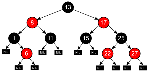
An example of a red–black tree
A red–black tree is a binary search tree where each node has a color attribute, the value of which is either red or black. In addition to the ordinary requirements imposed on binary search trees, the following requirements apply to red–black trees:
  1. A node is either red or black.
  2. The root is black. (This rule is sometimes omitted from other definitions. Since the root can always be changed from red to black, but not necessarily vice-versa, this rule has little effect on analysis.)
  3. All leaves are the same color as the root.
  4. Both children of every red node are black.
  5. Every simple path from a given node to any of its descendant leaves contains the same number of black nodes.
These constraints enforce a critical property of red–black trees: that the path from the root to the furthest leaf is no more than twice as long as the path from the root to the nearest leaf. The result is that the tree is roughly balanced. Since operations such as inserting, deleting, and finding values require worst-case time proportional to the height of the tree, this theoretical upper bound on the height allows red–black trees to be efficient in the worst-case, unlike ordinary binary search trees.
To see why this is guaranteed, it suffices to consider the effect of properties 4 and 5 together. For a red–black tree T, let B be the number of black nodes in property 5. Therefore the shortest possible path from the root of T to any leaf consists of B black nodes. Longer possible paths may be constructed by inserting red nodes. However, property 4 makes it impossible to insert more than one consecutive red node. Therefore the longest possible path consists of 2B nodes, alternating black and red.
The shortest possible path has all black nodes, and the longest possible path alternates between red and black nodes. Since all maximal paths have the same number of black nodes, by property 5, this shows that no path is more than twice as long as any other path.
In many of the presentations of tree data structures, it is possible for a node to have only one child, and leaf nodes contain data. It is possible to present red–black trees in this paradigm, but it changes several of the properties and complicates the algorithms. For this reason, this article uses "null leaves", which contain no data and merely serve to indicate where the tree ends, as shown above. These nodes are often omitted in drawings, resulting in a tree that seems to contradict the above principles, but in fact does not. A consequence of this is that all internal (non-leaf) nodes have two children, although one or both of those children may be null leaves. Property 5 ensures that a red node must have either two black null leaves or two black non-leaves as children. For a black node with one null leaf child and one non-null-leaf child, properties 3, 4 and 5 ensure that the non-null-leaf child must be a red node with two black null leaves as children.
Some explain a red–black tree as a binary search tree whose edges, instead of nodes, are colored in red or black, but this does not make any difference. The color of a node in this article's terminology corresponds to the color of the edge connecting the node to its parent, except that the root node is always black (property 2) whereas the corresponding edge does not exist.

Diagram of binary tree. The black root node has two red children and four black grandchildren. The child nodes of the grandchildren are either black nil pointers or red nodes with black nil pointers.

[edit] Analogy to B-trees of order 4


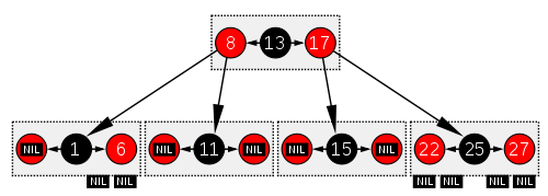
The same red–black tree as in the example above, seen as a B-tree.
A red–black tree is similar in structure to a B-tree of order 4, where each node can contain between 1 to 3 values and (accordingly) between 2 to 4 child pointers. In such B-tree, each node will contain only one value matching the value in a black node of the red–black tree, with an optional value before and/or after it in the same node, both matching an equivalent red node of the red–black tree.
One way to see this equivalence is to "move up" the red nodes in a graphical representation of the red–black tree, so that they align horizontally with their parent black node, by creating together a horizontal cluster. In the B-tree, or in the modified graphical representation of the red–black tree, all leaf nodes are at the same depth.
The red–black tree is then structurally equivalent to a B-tree of order 4, with a minimum fill factor of 33% of values per cluster with a maximum capacity of 3 values.
This B-tree type is still more general than a red–black tree though, as it allows ambiguity in a red–black tree conversion—multiple red–black trees can be produced from an equivalent B-tree of order 4. If a B-tree cluster contains only 1 value, it is the minimum, black, and has two child pointers. If a cluster contains 3 values, then the central value will be black and each value stored on its sides will be red. If the cluster contains two values, however, either one can become the black node in the red–black tree (and the other one will be red).
So the order-4 B-tree does not maintain which of the values contained in each cluster is the root black tree for the whole cluster and the parent of the other values in the same cluster. Despite this, the operations on red–black trees are more economical in time because you don't have to maintain the vector of values. It may be costly if values are stored directly in each node rather than being stored by reference. B-tree nodes, however, are more economical in space because you don't need to store the color attribute for each node. Instead, you have to know which slot in the cluster vector is used. If values are stored by reference, e.g. objects, null references can be used and so the cluster can be represented by a vector containing 3 slots for value pointers plus 4 slots for child references in the tree. In that case, the B-tree can be more compact in memory, improving data locality.
The same analogy can be made with B-trees with larger orders that can be structurally equivalent to a colored binary tree: you just need more colors. Suppose that you add blue, then the blue–red–black tree defined like red–black trees but with the additional constraint that no two successive nodes in the hierarchy will be blue and all blue nodes will be children of a red node, then it becomes equivalent to a B-tree whose clusters will have at most 7 values in the following colors: blue, red, blue, black, blue, red, blue (For each cluster, there will be at most 1 black node, 2 red nodes, and 4 blue nodes).
For moderate volumes of values, insertions and deletions in a colored binary tree are faster compared to B-trees because colored trees don't attempt to maximize the fill factor of each horizontal cluster of nodes (only the minimum fill factor is guaranteed in colored binary trees, limiting the number of splits or junctions of clusters). B-trees will be faster for performing rotations (because rotations will frequently occur within the same cluster rather than with multiple separate nodes in a colored binary tree). However for storing large volumes, B-trees will be much faster as they will be more compact by grouping several children in the same cluster where they can be accessed locally.
All optimizations possible in B-trees to increase the average fill factors of clusters are possible in the equivalent multicolored binary tree. Notably, maximizing the average fill factor in a structurally equivalent B-tree is the same as reducing the total height of the multicolored tree, by increasing the number of non-black nodes. The worst case occurs when all nodes in a colored binary tree are black, the best case occurs when only a third of them are black (and the other two thirds are red nodes).

[edit] Applications and related data structures

Red–black trees offer worst-case guarantees for insertion time, deletion time, and search time. Not only does this make them valuable in time-sensitive applications such as real-time applications, but it makes them valuable building blocks in other data structures which provide worst-case guarantees; for example, many data structures used in computational geometry can be based on red–black trees, and the Completely Fair Scheduler used in current Linux kernels uses red–black trees.
The AVL tree is another structure supporting O(log n) search, insertion, and removal. It is more rigidly balanced than red–black trees, leading to slower insertion and removal but faster retrieval. This makes it attractive for data structures that may be built once and loaded without reconstruction, such as language dictionaries (or program dictionaries, such as the opcodes of an assembler or interpreter).
Red–black trees are also particularly valuable in functional programming, where they are one of the most common persistent data structures, used to construct associative arrays and sets which can retain previous versions after mutations. The persistent version of red–black trees requires O(log n) space for each insertion or deletion, in addition to time.
For every 2-4 tree, there are corresponding red–black trees with data elements in the same order. The insertion and deletion operations on 2-4 trees are also equivalent to color-flipping and rotations in red–black trees. This makes 2-4 trees an important tool for understanding the logic behind red–black trees, and this is why many introductory algorithm texts introduce 2-4 trees just before red–black trees, even though 2-4 trees are not often used in practice.
In 2008, Sedgewick introduced a simpler version of red–black trees called Left-Leaning Red–Black Trees[3] by eliminating a previously unspecified degree of freedom in the implementation. The LLRB maintains an additional invariant that all red links must lean left except during inserts and deletes. Red–black trees can be made isometric to either 2-3 trees,[4] or 2-4 trees,[3] for any sequence of operations. The 2-4 tree isometry was described in 1978 by Sedgewick. With 2-4 trees, the isometry is resolved by a "color flip," corresponding to a split, in which the red color of two children nodes leaves the children and moves to the parent node. The tango tree, a type of tree optimized for fast searches, usually uses red–black trees as part of its data structure.

[edit] Operations

Read-only operations on a red–black tree require no modification from those used for binary search trees, because every red–black tree is a special case of a simple binary search tree. However, the immediate result of an insertion or removal may violate the properties of a red–black tree. Restoring the red–black properties requires a small number (O(log n) or amortized O(1)) of color changes (which are very quick in practice) and no more than three tree rotations (two for insertion). Although insert and delete operations are complicated, their times remain O(log n).

[edit] Insertion

Insertion begins by adding the node much as binary search tree insertion does and by coloring it red. Whereas in the binary search tree, we always add a leaf, in the red–black tree leaves contain no information, so instead we add a red interior node, with two black leaves, in place of an existing black leaf.
What happens next depends on the color of other nearby nodes. The term uncle node will be used to refer to the sibling of a node's parent, as in human family trees. Note that:
  • Property 3 (All leaves are black) always holds.
  • Property 4 (Both children of every red node are black) is threatened only by adding a red node, repainting a black node red, or a rotation.
  • Property 5 (All paths from any given node to its leaf nodes contain the same number of black nodes) is threatened only by adding a black node, repainting a red node black (or vice versa), or a rotation.
Note: The label N will be used to denote the current node (colored red). At the beginning, this is the new node being inserted, but the entire procedure may also be applied recursively to other nodes (see case 3). P will denote N's parent node, G will denote N's grandparent, and U will denote N's uncle. Note that in between some cases, the roles and labels of the nodes are exchanged, but in each case, every label continues to represent the same node it represented at the beginning of the case. Any color shown in the diagram is either assumed in its case or implied by those assumptions.
Each case will be demonstrated with example C code. The uncle and grandparent nodes can be found by these functions:
struct node *grandparent(struct node *n)
{
        if ((n != NULL) && (n->parent != NULL))
                return n->parent->parent;
        else
                return NULL;
}
 
struct node *uncle(struct node *n)
{
        struct node *g = grandparent(n);
        if (g == NULL)
                return NULL; // No grandparent means no uncle
        if (n->parent == g->left)
                return g->right;
        else
                return g->left;
}
Case 1: The current node N is at the root of the tree. In this case, it is repainted black to satisfy Property 2 (The root is black). Since this adds one black node to every path at once, Property 5 (All paths from any given node to its leaf nodes contain the same number of black nodes) is not violated.
void insert_case1(struct node *n)
{
        if (n->parent == NULL)
                n->color = BLACK;
        else
                insert_case2(n);
}
Case 2: The current node's parent P is black, so Property 4 (Both children of every red node are black) is not invalidated. In this case, the tree is still valid. Property 5 (All paths from any given node to its leaf nodes contain the same number of black nodes) is not threatened, because the current node N has two black leaf children, but because N is red, the paths through each of its children have the same number of black nodes as the path through the leaf it replaced, which was black, and so this property remains satisfied.
void insert_case2(struct node *n)
{
        if (n->parent->color == BLACK)
                return; /* Tree is still valid */
        else
                insert_case3(n);
}
Note: In the following cases it can be assumed that N has a grandparent node G, because its parent P is red, and if it were the root, it would be black. Thus, N also has an uncle node U, although it may be a leaf in cases 4 and 5.
Diagram of case 3
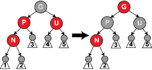
Case 3: If both the parent P and the uncle U are red, then both of them can be repainted black and the grandparent G becomes red (to maintain Property 5 (All paths from any given node to its leaf nodes contain the same number of black nodes)). Now, the current red node N has a black parent. Since any path through the parent or uncle must pass through the grandparent, the number of black nodes on these paths has not changed. However, the grandparent G may now violate properties 2 (The root is black) or 4 (Both children of every red node are black) (property 4 possibly being violated since G may have a red parent). To fix this, the entire procedure is recursively performed on G from case 1. Note that this is a tail-recursive call, so it could be rewritten as a loop; since this is the only loop, and any rotations occur after this loop, this proves that a constant number of rotations occur.
void insert_case3(struct node *n)
{
        struct node *u = uncle(n), *g;
 
        if ((u != NULL) && (u->color == RED)) {
                n->parent->color = BLACK;
                u->color = BLACK;
                g = grandparent(n);
                g->color = RED;
                insert_case1(g);
        } else {
                insert_case4(n);
        }
}
Note: In the remaining cases, it is assumed that the parent node P is the left child of its parent. If it is the right child, left and right should be reversed throughout cases 4 and 5. The code samples take care of this.
Diagram of case 4
Case 4: The parent P is red but the uncle U is black; also, the current node N is the right child of P, and P in turn is the left child of its parent G. In this case, a left rotation that switches the roles of the current node N and its parent P can be performed; then, the former parent node P is dealt with using Case 5 (relabeling N and P) because property 4 (Both children of every red node are black) is still violated. The rotation causes some paths (those in the sub-tree labelled "1") to pass through the node N where they did not before. It also causes some paths (those in the sub-tree labelled "3") not to pass through the node P where they did before. However, both of these nodes are red, so Property 5 (All paths from any given node to its leaf nodes contain the same number of black nodes) is not violated by the rotation. After this case has been completed, Property 4 (both children of every red node are black) is still violated, but now we can resolve this by continuing to Case 5.
void insert_case4(struct node *n)
{
        struct node *g = grandparent(n);
 
        if ((n == n->parent->right) && (n->parent == g->left)) {
                rotate_left(n->parent);
                n = n->left;
        } else if ((n == n->parent->left) && (n->parent == g->right)) {
                rotate_right(n->parent);
                n = n->right;
        }
        insert_case5(n);
}
Diagram of case 5
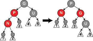
Case 5: The parent P is red but the uncle U is black, the current node N is the left child of P, and P is the left child of its parent G. In this case, a right rotation on G is performed; the result is a tree where the former parent P is now the parent of both the current node N and the former grandparent G. G is known to be black, since its former child P could not have been red otherwise (without violating Property 4). Then, the colors of P and G are switched, and the resulting tree satisfies Property 4 (Both children of every red node are black). Property 5 (All paths from any given node to its leaf nodes contain the same number of black nodes) also remains satisfied, since all paths that went through any of these three nodes went through G before, and now they all go through P. In each case, this is the only black node of the three.
void insert_case5(struct node *n)
{
        struct node *g = grandparent(n);
 
        n->parent->color = BLACK;
        g->color = RED;
        if ((n == n->parent->left) && (n->parent == g->left)) {
                rotate_right(g);
        } else if ((n == n->parent->right) && (n->parent == g->right)) {
                rotate_left(g);
        }
}
Note that inserting is actually in-place, since all the calls above use tail recursion.

[edit] Removal

In a regular binary search tree, when deleting a node with two non-leaf children, we find either the maximum element in its left subtree (which is the in-order predecessor) or the minimum element in its right subtree (which is the in-order successor) and move its value into the node being deleted (as shown here). We then delete the node we copied the value from, which must have fewer than two non-leaf children. (Non-leaf children, rather than all children, are specified here because unlike normal binary search trees, red–black trees have leaf nodes anywhere they can have them, so that all nodes are either internal nodes with two children or leaf nodes with, by definition, zero children. In effect, internal nodes having two leaf children in a red–black tree are like the leaf nodes in a regular binary search tree.) Because merely copying a value does not violate any red–black properties, this reduces to the problem of deleting a node with at most one non-leaf child. Once we have solved that problem, the solution applies equally to the case where the node we originally want to delete has at most one non-leaf child as to the case just considered where it has two non-leaf children.
Therefore, for the remainder of this discussion we address the deletion of a node with at most one non-leaf child. We use the label M to denote the node to be deleted; C will denote a selected child of M, which we will also call "its child". If M does have a non-leaf child, call that its child, C; otherwise, choose either leaf as its child, C.
If M is a red node, we simply replace it with its child C, which must be black by definition. (This can only occur when M has two leaf children, because if the red node M had a black non-leaf child on one side but just a leaf child on the other side, then the count of black nodes on both sides would be different, thus the tree would had been an invalid red–black tree by violation of Property 5.) All paths through the deleted node will simply pass through one less red node, and both the deleted node's parent and child must be black, so Property 3 (“All leaves are black”) and Property 4 (“Both children of every red node are black”) still hold.
Another simple case is when M is black and C is red. Simply removing a black node could break Properties 4 (“Both children of every red node are black”) and 5 (“All paths from any given node to its leaf nodes contain the same number of black nodes”), but if we repaint C black, both of these properties are preserved.
The complex case is when both M and C are black. (This can only occur when deleting a black node which has two leaf children, because if the black node M had a black non-leaf child on one side but just a leaf child on the other side, then the count of black nodes on both sides would be different, thus the tree would had been an invalid red–black tree by violation of Property 5.) We begin by replacing M with its child C. We will call (or label—that is, relabel) this child (in its new position) N, and its sibling (its new parent's other child) S. (S was previously the sibling of M.) In the diagrams below, we will also use P for N's new parent (M's old parent), SL for S's left child, and SR for S's right child (S cannot be a leaf because if N is black, which we presumed, then P's one subtree which includes N counts two black-height and thus P's other subtree which includes S must also count two black-height, which cannot be the case if S is a leaf node).
Note: In between some cases, we exchange the roles and labels of the nodes, but in each case, every label continues to represent the same node it represented at the beginning of the case. Any color shown in the diagram is either assumed in its case or implied by those assumptions. White represents an unknown color (either red or black).
We will find the sibling using this function:
struct node *sibling(struct node *n)
{
        if (n == n->parent->left)
                return n->parent->right;
        else
                return n->parent->left;
}
Note: In order that the tree remains well-defined, we need that every null leaf remains a leaf after all transformations (that it will not have any children). If the node we are deleting has a non-leaf (non-null) child N, it is easy to see that the property is satisfied. If, on the other hand, N would be a null leaf, it can be verified from the diagrams (or code) for all the cases that the property is satisfied as well.
We can perform the steps outlined above with the following code, where the function replace_node substitutes child into n's place in the tree. For convenience, code in this section will assume that null leaves are represented by actual node objects rather than NULL (the code in the Insertion section works with either representation).
void delete_one_child(struct node *n)
{
        /*
         * Precondition: n has at most one non-null child.
         */
        struct node *child = is_leaf(n->right) ? n->left : n->right;
 
        replace_node(n, child);
        if (n->color == BLACK) {
                if (child->color == RED)
                        child->color = BLACK;
                else
                        delete_case1(child);
        }
        free(n);
}
Note: If N is a null leaf and we do not want to represent null leaves as actual node objects, we can modify the algorithm by first calling delete_case1() on its parent (the node that we delete, n in the code above) and deleting it afterwards. We can do this because the parent is black, so it behaves in the same way as a null leaf (and is sometimes called a 'phantom' leaf). And we can safely delete it at the end as n will remain a leaf after all operations, as shown above.
If both N and its original parent are black, then deleting this original parent causes paths which proceed through N to have one fewer black node than paths that do not. As this violates Property 5 (All paths from any given node to its leaf nodes contain the same number of black nodes), the tree must be rebalanced. There are several cases to consider:
Case 1: N is the new root. In this case, we are done. We removed one black node from every path, and the new root is black, so the properties are preserved.
void delete_case1(struct node *n)
{
        if (n->parent != NULL)
                delete_case2(n);
}
Note: In cases 2, 5, and 6, we assume N is the left child of its parent P. If it is the right child, left and right should be reversed throughout these three cases. Again, the code examples take both cases into account.
Diagram of case 2
Case 2: S is red. In this case we reverse the colors of P and S, and then rotate left at P, turning S into N's grandparent. Note that P has to be black as it had a red child. Although all paths still have the same number of black nodes, now N has a black sibling and a red parent, so we can proceed to step 4, 5, or 6. (Its new sibling is black because it was once the child of the red S.) In later cases, we will relabel N's new sibling as S.
void delete_case2(struct node *n)
{
        struct node *s = sibling(n);
 
        if (s->color == RED) {
                n->parent->color = RED;
                s->color = BLACK;
                if (n == n->parent->left)
                        rotate_left(n->parent);
                else
                        rotate_right(n->parent);
        } 
        delete_case3(n);
}
Diagram of case 3
Case 3: P, S, and S's children are black. In this case, we simply repaint S red. The result is that all paths passing through S, which are precisely those paths not passing through N, have one less black node. Because deleting N's original parent made all paths passing through N have one less black node, this evens things up. However, all paths through P now have one fewer black node than paths that do not pass through P, so Property 5 (All paths from any given node to its leaf nodes contain the same number of black nodes) is still violated. To correct this, we perform the rebalancing procedure on P, starting at case 1.
void delete_case3(struct node *n)
{
        struct node *s = sibling(n);
 
        if ((n->parent->color == BLACK) &&
            (s->color == BLACK) &&
            (s->left->color == BLACK) &&
            (s->right->color == BLACK)) {
                s->color = RED;
                delete_case1(n->parent);
        } else
                delete_case4(n);
}
Diagram of case 4
Case 4: S and S's children are black, but P is red. In this case, we simply exchange the colors of S and P. This does not affect the number of black nodes on paths going through S, but it does add one to the number of black nodes on paths going through N, making up for the deleted black node on those paths.
void delete_case4(struct node *n)
{
        struct node *s = sibling(n);
 
        if ((n->parent->color == RED) &&
            (s->color == BLACK) &&
            (s->left->color == BLACK) &&
            (s->right->color == BLACK)) {
                s->color = RED;
                n->parent->color = BLACK;
        } else
                delete_case5(n);
}
Diagram of case 5
Case 5: S is black, S's left child is red, S's right child is black, and N is the left child of its parent. In this case we rotate right at S, so that S's left child becomes S's parent and N's new sibling. We then exchange the colors of S and its new parent. All paths still have the same number of black nodes, but now N has a black sibling whose right child is red, so we fall into case 6. Neither N nor its parent are affected by this transformation. (Again, for case 6, we relabel N's new sibling as S.)
void delete_case5(struct node *n)
{
        struct node *s = sibling(n);
 
        if  (s->color == BLACK) { /* this if statement is trivial, 
due to Case 2 (even though Case two changed the sibling to a sibling's child, 
the sibling's child can't be red, since no red parent can have a red child). */
/* the following statements just force the red to be on the left of the left of the parent, 
   or right of the right, so case six will rotate correctly. */
                if ((n == n->parent->left) &&
                    (s->right->color == BLACK) &&
                    (s->left->color == RED)) { /* this last test is trivial too due to cases 2-4. */
                        s->color = RED;
                        s->left->color = BLACK;
                        rotate_right(s);
                } else if ((n == n->parent->right) &&
                           (s->left->color == BLACK) &&
                           (s->right->color == RED)) {/* this last test is trivial too due to cases 2-4. */
                        s->color = RED;
                        s->right->color = BLACK;
                        rotate_left(s);
                }
        }
        delete_case6(n);
}
Diagram of case 6
Case 6: S is black, S's right child is red, and N is the left child of its parent P. In this case we rotate left at P, so that S becomes the parent of P and S's right child. We then exchange the colors of P and S, and make S's right child black. The subtree still has the same color at its root, so Properties 4 (Both children of every red node are black) and 5 (All paths from any given node to its leaf nodes contain the same number of black nodes) are not violated. However, N now has one additional black ancestor: either P has become black, or it was black and S was added as a black grandparent. Thus, the paths passing through N pass through one additional black node.
Meanwhile, if a path does not go through N, then there are two possibilities:
  • It goes through N's new sibling. Then, it must go through S and P, both formerly and currently, as they have only exchanged colors and places. Thus the path contains the same number of black nodes.
  • It goes through N's new uncle, S's right child. Then, it formerly went through S, S's parent, and S's right child (which was red), but now only goes through S, which has assumed the color of its former parent, and S's right child, which has changed from red to black (assuming S's color: black). The net effect is that this path goes through the same number of black nodes.
Either way, the number of black nodes on these paths does not change. Thus, we have restored Properties 4 (Both children of every red node are black) and 5 (All paths from any given node to its leaf nodes contain the same number of black nodes). The white node in the diagram can be either red or black, but must refer to the same color both before and after the transformation.
void delete_case6(struct node *n)
{
        struct node *s = sibling(n);
 
        s->color = n->parent->color;
        n->parent->color = BLACK;
 
        if (n == n->parent->left) {
                s->right->color = BLACK;
                rotate_left(n->parent);
        } else {
                s->left->color = BLACK;
                rotate_right(n->parent);
        }
}
Again, the function calls all use tail recursion, so the algorithm is in-place. In the algorithm above, all cases are chained in order, except in delete case 3 where it can recurse to case 1 back to the parent node: this is the only case where an in-place implementation will effectively loop (after only one rotation in case 3).
Additionally, no tail recursion ever occurs on a child node, so the tail recursion loop can only move from a child back to its successive ancestors. No more than O(log n) loops back to case 1 will occur (where n is the total number of nodes in the tree before deletion). If a rotation occurs in case 2 (which is the only possibility of rotation within the loop of cases 1–3), then the parent of the node N becomes red after the rotation and we will exit the loop. Therefore at most one rotation will occur within this loop. Since no more than two additional rotations will occur after exiting the loop, at most three rotations occur in total.

[edit] Proof of asymptotic bounds

A red black tree which contains n internal nodes has a height of O(log(n)).
Definitions:
  • h(v) = height of subtree rooted at node v
  • bh(v) = the number of black nodes (not counting v if it is black) from v to any leaf in the subtree (called the black-height).
Lemma: A subtree rooted at node v has at least 2bh(v) − 1 internal nodes.
Proof of Lemma (by induction height):
Basis: h(v) = 0
If v has a height of zero then it must be null, therefore bh(v) = 0. So:
2bh(v) − 1 = 20 − 1 = 1 − 1 = 0
Inductive Step: v such that h(v) = k, has at least 2bh(v) − 1 internal nodes implies that v' such that h(v') = k+1 has at least 2bh(v') − 1 internal nodes.
Since v' has h(v') > 0 it is an internal node. As such it has two children each of which have a black-height of either bh(v') or bh(v')-1 (depending on whether the child is red or black, respectively). By the inductive hypothesis each child has at least 2bh(v') − 1 − 1 internal nodes, so v' has at least:
2bh(v') − 1 − 1 + 2bh(v') − 1 − 1 + 1 = 2bh(v') − 1
internal nodes.
Using this lemma we can now show that the height of the tree is logarithmic. Since at least half of the nodes on any path from the root to a leaf are black (property 4 of a red black tree), the black-height of the root is at least h(root)/2. By the lemma we get:
n \geq 2^{{h(\text{root}) \over 2}} - 1 \leftrightarrow \; \log_2{(n+1)} \geq {h(\text{root}) \over 2} \leftrightarrow \; h(\text{root}) \leq 2\log_2{(n+1)}.
Therefore the height of the root is O(log(n)).

[edit] Insertion complexity

In the tree code there is only one loop where the node of the root of the red–black property that we wish to restore, x, can be moved up the tree by one level at each iteration.
Since the original height of the tree is O(log n), there are O(log n) iterations. So overall the insert routine has O(log n) complexity.

[edit] Parallel algorithms

Parallel algorithms for constructing red–black trees from sorted lists of items can run in constant time or O(loglog n) time, depending on the computer model, if the number of processors available is proportional to the number of items. Fast search, insertion, and deletion parallel algorithms are also known.[5]

[edit] See also


Notes

  1. ^ Rudolf Bayer (1972). "Symmetric binary B-Trees: Data structure and maintenance algorithms". Acta Informatica 1 (4): 290–306. doi:10.1007/BF00289509.
  2. ^ Leonidas J. Guibas and Robert Sedgewick (1978). "A Dichromatic Framework for Balanced Trees". Proceedings of the 19th Annual Symposium on Foundations of Computer Science. pp. 8–21. doi:10.1109/SFCS.1978.3.
  3. ^ a b http://www.cs.princeton.edu/~rs/talks/LLRB/RedBlack.pdf
  4. ^ http://www.cs.princeton.edu/courses/archive/fall08/cos226/lectures/10BalancedTrees-2x2.pdf
  5. ^ H. Park and K. Park (2001). "Parallel algorithms for red–black trees". Theoretical computer science (Elsevier) 262 (1–2): 415–435. doi:10.1016/S0304-3975(00)00287-5.

[edit] References

[edit] External links